SAMD11 and SAMD21 Arduino Toolchain
- Arduino?
- Arduino on Fab Boards !
- 1: Schematic Requirements
- 2: Bootloader Install
- 3: Arduino Setup
- 4: Pin Mapping?
- 5: Pin Mapping Tables
- Programming in Arduino
Arduino?
Arduino is an open source project that uses a few software shims to make the microcontroller programming experience easier for beginners. When we write arduino code, we are really just writing in cpp within an IDE that can be configured to build the same code for any supported circuit. Basically, it takes all of the complexity mentioned previously and bottles it up into a standalone IDE / toolchain. So - useful!
Arduino can be installed by downloading it here - this includes everything you’ll need: compiler, drivers, etc.
Arduino on Fab Boards !
We have taken to using Arduino in order to program fab lab circuits, a workflow that is especially popular with the SAMD11 and SAMD21 circuits - it also works with the ESP32.
Major credit to Quentin Bolsee for his work on a ‘fab’ arduino core that makes this possible, and to Justin Mattair who started the project.
1: Schematic Requirements
In order to do any of this, our schematic and circuit board needs to include the basics:
- power and communication to the board (here, a USB hookup)
- voltage regulation
- USB offers +5v power up to 500ma, our micros want +3v3, so we regul8
- bypass capacitors
- these help stablize voltage inputs to the microcontroller
- a debug / programming port
- we need this in order to load the bootloader
I am including ‘basics’ schematics / board layouts for each of these. ATSAMD11D/C designs courtesy of Neil.
| micro | schematic / notes | board |
|---|---|---|
| ATSAMD11C | IC2 is the 3v3 output regulator.no bypass caps here, but they never hurt to add. | 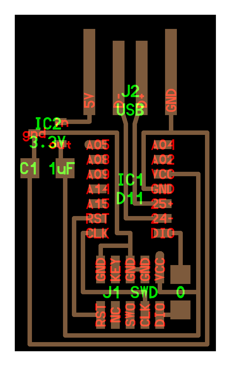 |
| ATSAMD11D | IC2 is the 3v3 output regulator.no bypass caps here either. | 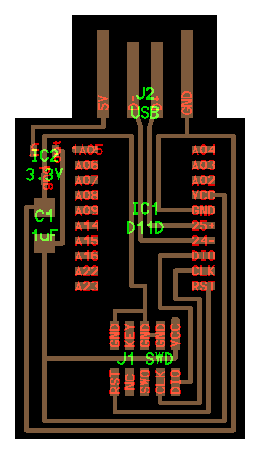 |
| ATSAMD21E18A | 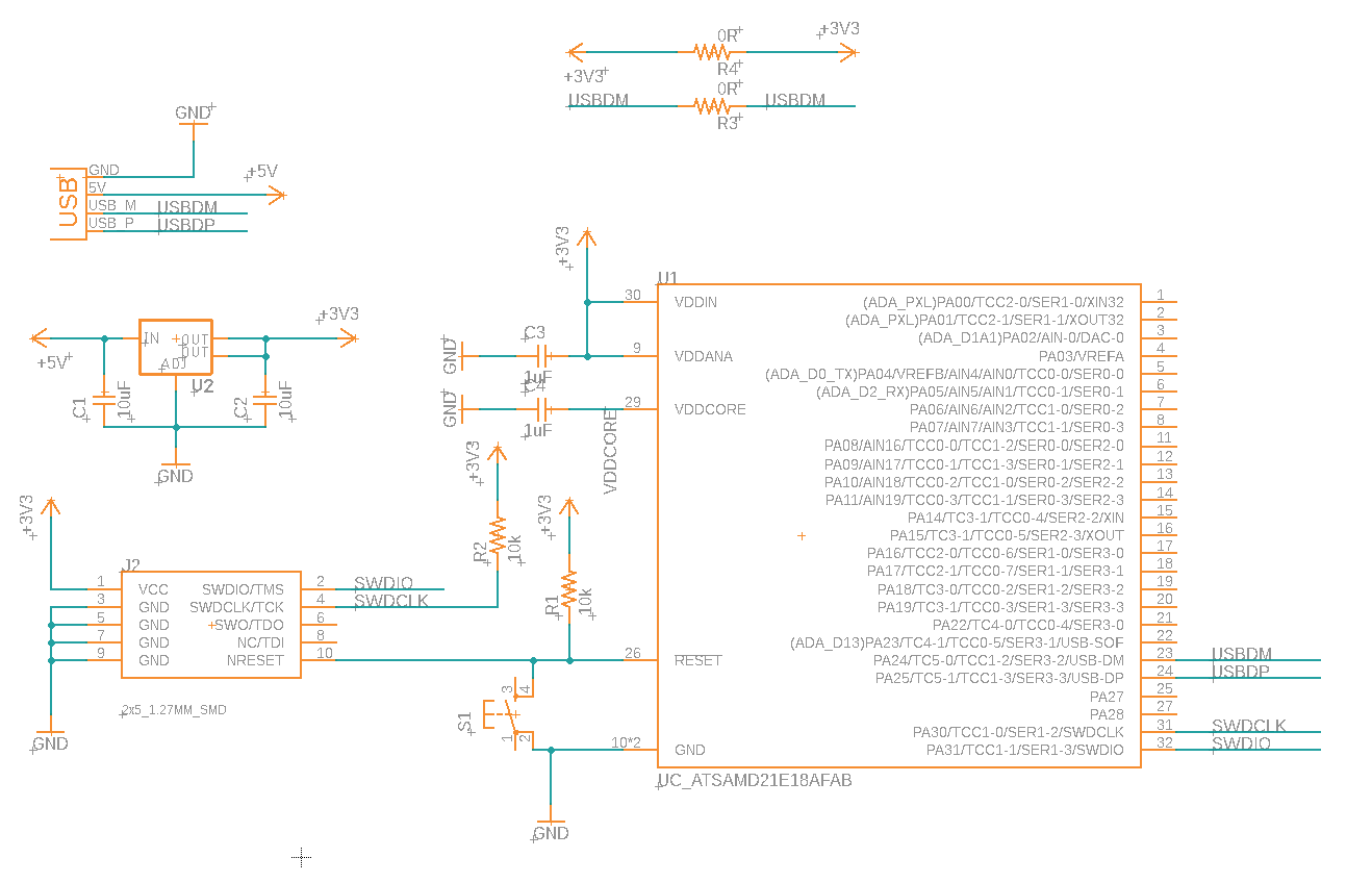 | 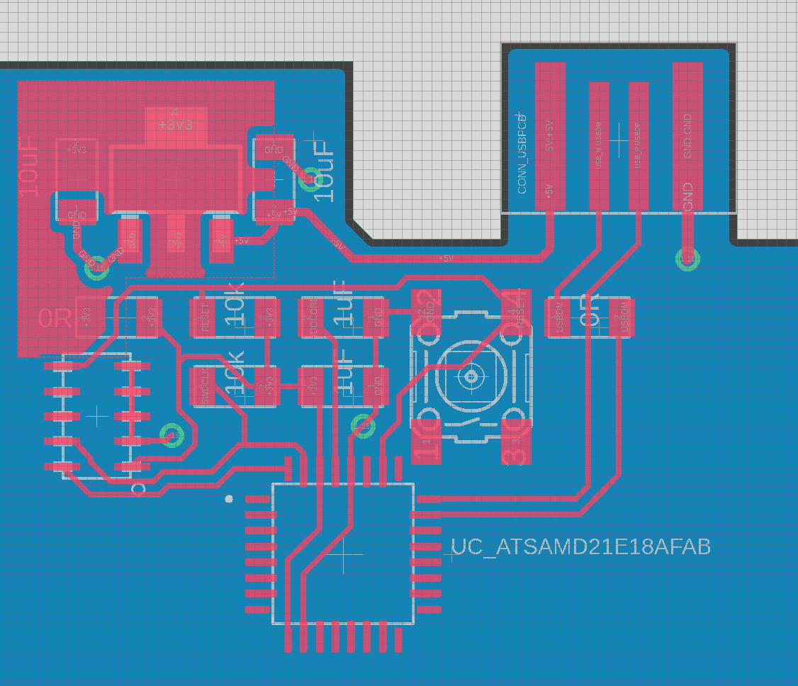 |
2: Bootloader Install
The arduino bootloader is a key feature of the platform: this allows arduino the IDE and compiler to load programs onto your board, so we need to first program that bootloader onto your new board.
For the ATSAMD11 and ATSAMD21 series microcontrollers, this means finding one of the cmsis-dap tools and using edbg, pyOCD or openOCD in order to load the bootloader binary on the board. That binary is specific to whichever microcontroller you’re using:
Once that’s loaded (via those SWD pins), we can plug the board in via USB to program and communicate with it.
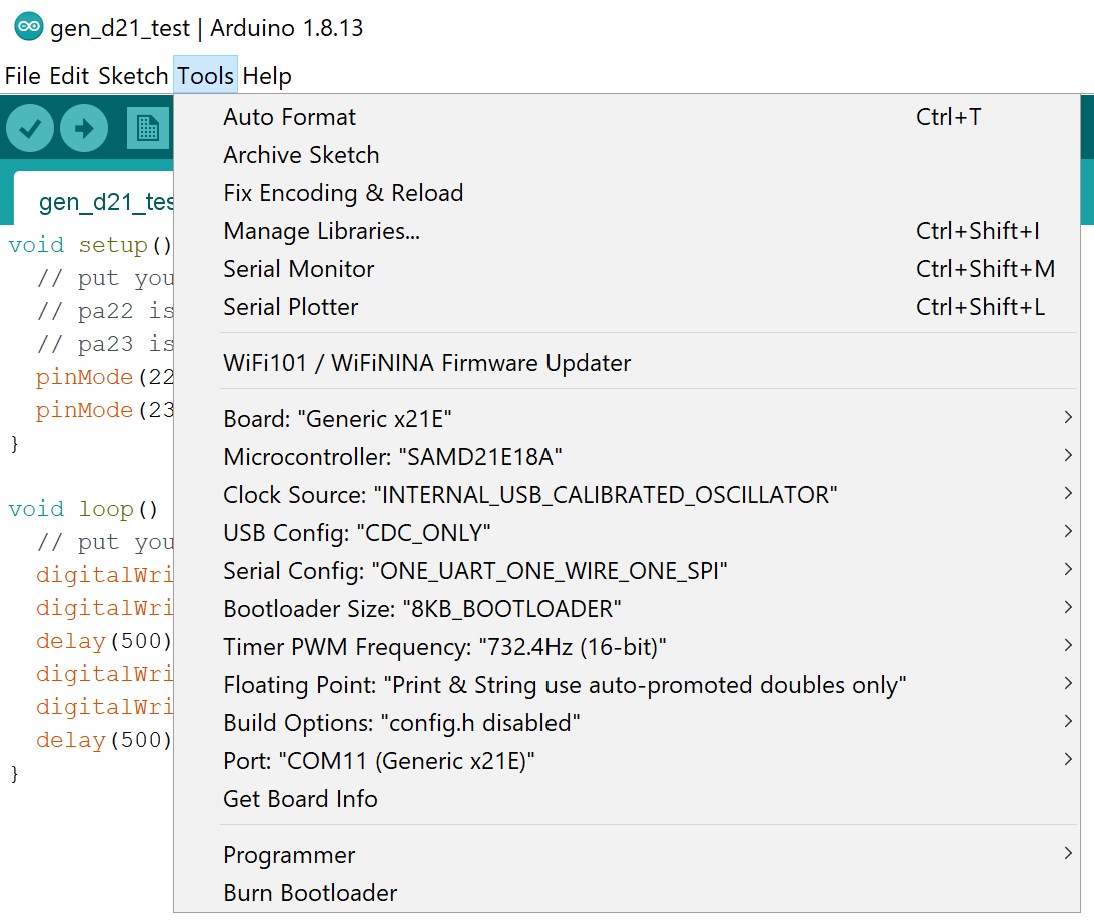
3: Arduino Setup
These boards aren’t supported by arduino out of the box. In order to make that happen, we need to open up arduino and do:
file -> preferences -> additional board manager URLS- add this link:
https://raw.githubusercontent.com/qbolsee/ArduinoCore-fab-sam/master/json/package_Fab_SAM_index.json
- add this link:
- now arduino will be able to find the “board definitions” when we do:
tools -> board -> board manager- search for
Fab SAM core for Arduino - hit
install
- search for
Once this is setup, we can use arduino to write code, easy! When doing so, make sure you have the right arduino settings, and that the board appears in the port menu:
4: Pin Mapping?
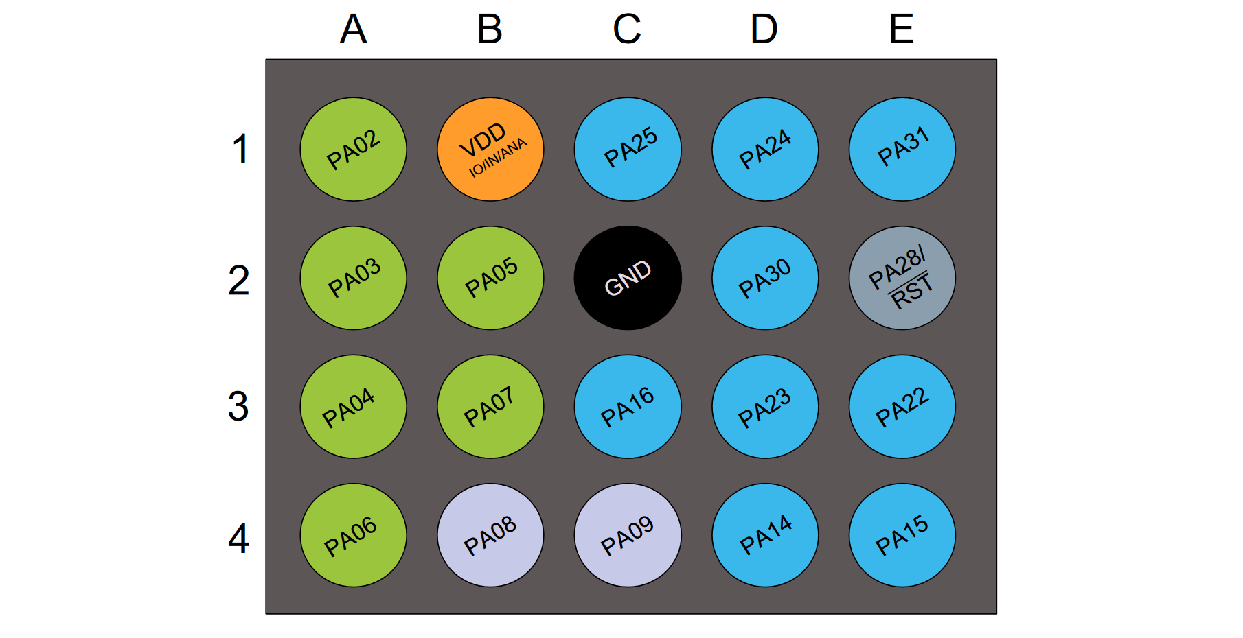
One devious shim that arduino inserts into the toolchain is a pin mapping. For some explanation, recall that when designing a circuit we normally keep track of which “pin number” is connected to which circuit trace / net. In this case, we’re probably interested in the physical microcontroller pin, but also the port/pin number that the uC uses in its SFRs in order to switch it on / off, receive data on it, etc:
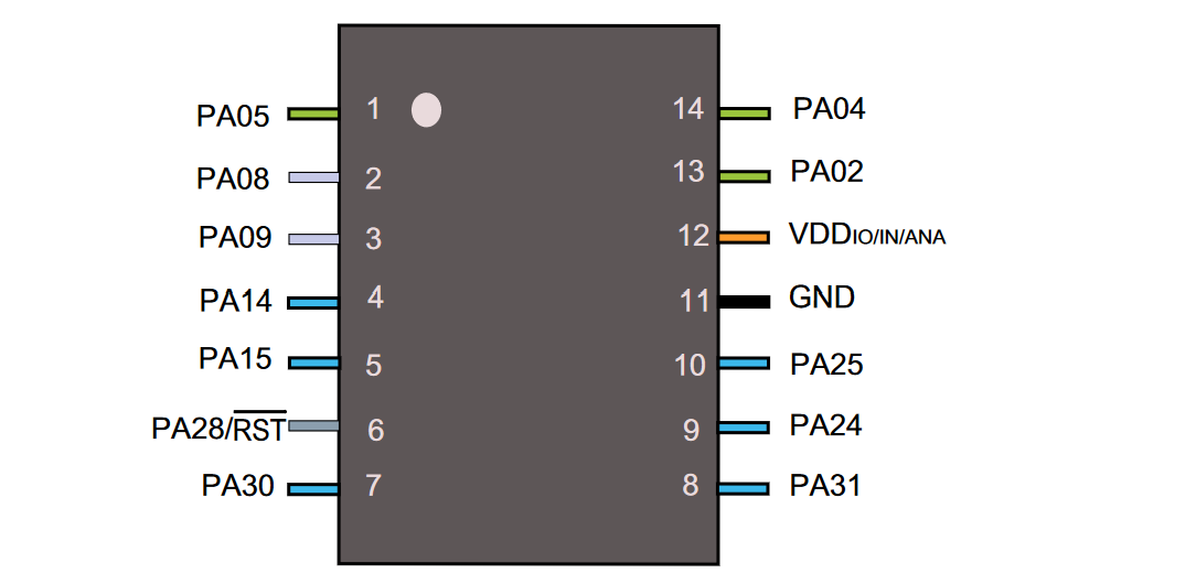
The physical pins (here, 1 through 14) are not related to the SFR / software pins (here, PA02, PA04, PA05, PA08, PA09, PA14, PA15, PA24, PA25, PA28, PA30, PA31) - this is because we often see different physical packages with the same silicon die inside, a-la:
And then arduino gets involved and makes boards like this:
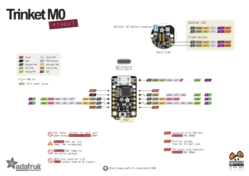
Shoutout to adafruit, who does a wonderful job of documenting their boards. This trinket, for example, implements a SAMD21E18A (which has ~ 28 pins) but breaks out only 5 of them. In arduino, these are mapped with numbers 0, 1, 2, 3, 4 but correspond actually to physical SAMD21 pins 11, 3, 12, 8, 7 and SFR addresses PA08, PA02, PA09, PA07, PA06.
This mapping can make homebrew circuits confusing when we’re using arduino to program them, thankfully the arduino core we’re using documents the mappings below.
5: Pin Mapping Tables
And I’m copying them out here, as a treat:
====================================== ATsamD11C14A =====================================
Other  COM   PWM  Analog  INT  Arduino*           Arduino*  INT  Analog  PWM   COM  Other
=========================================================================================
                                  1-------------------
  SCK*/RX2  TCC01    *     *    5 | A5             A4 | 4    *    *  TCC00 MOSI*/TX2  REF
    MOSI*   TCC02          *    8 | A8 (XIN)       A2 | 2    *    *                   DAC
    SCK*    TCC03          *    9 | A9 (XOUT)     Vdd |
  SDA/MISO*  TC10    *    NMI  14 | A14           Gnd |
   SCL/SS*   TC11    *     *   15 | A15           A25 | 25                    USB/DP
BOOT                           28 | A28/RST       A24 | 24                    USB/DM
SWDCLK  TX1/MISO*              30 | A30           A31 | 31   *            RX1/SS*   SWDIO
                                   -------------------

* Most pins can be used for more than one function. When using PIN_MAP_STANDARD, the port
  pin number printed on the chip above is also used in Arduino (but without the 'A') for
  all of the supported functions (ie: digitalRead(), analogRead(), analogWrite(), etc.).
  When using PIN_MAP_COMPACT, the Arduino numbering is sequential starting from 0 at the
  top left pin (A5). PIN_MAP_COMPACT uses less FLASH.
* When USB CDC is enabled, Serial refers to SerialUSB, otherwise it refers to Serial1.
* When using ONE_UART_NO_WIRE_ONE_SPI, use SPI on pins 4, 5, 14, and 15.
  When using NO_UART_ONE_WIRE_ONE_SPI, use SPI on pins 8, 9, 30, and 31.
* Tone available on TC2. TC2 is not routed to pins in the D11C14A.
* Leave pin A30 floating (or use external pullup) during reset.
* DO NOT connect voltages higher than 3.3V!
=====================================  ATsamD11D14AS  ===================================
Other COM   PWM  Analog  INT  Arduino*            Arduino*  Analog  INT  PWM   COM  Other
=========================================================================================
                                   1-------------------
            TCC01    *     *    5  | A5             A4 | 4    *     *   TCC00        REFB
     SS     TCC02    *          6  | A6             A3 | 3    *                      REFA
    MISO    TCC03    *     *    7  | A7             A2 | 2    *     *                 DAC
Xin32/Xin                       8  | A8 (XIN)      Vdd |
Xout32/Xout                     9  | A9 (XOUT)     Gnd |
  MOSI/TX2           *    NMI   14 | A14           A25 | 25                  USB D+
  SCK/RX2   TC11     *     *    15 | A15           A24 | 24                  USB D-
            TC10           *    16 | A16           A31 | 31         *   TC21  RX1   SWDIO
    SDA                    *    22 | A22           A30 | 30             TC20  TX1  SWDCLK
    SCL                         23 | A23       RST/A28 | 28                          BOOT
                                    -------------------

* Most pins can be used for more than one function. When using PIN_MAP_STANDARD, the port
  pin number printed on the chip above is also used in Arduino (but without the 'A') for
  all of the supported functions (ie: digitalRead(), analogRead(), analogWrite(), etc.).
  When using PIN_MAP_COMPACT, the Arduino numbering is sequential starting from 0 at the
  top left pin (A5). PIN_MAP_COMPACT uses less FLASH.
* When USB CDC is enabled, Serial refers to SerialUSB, otherwise it refers to Serial1.
* Tone available on TC2.
* Leave pin A30 floating (or use external pullup) during reset.
* DO NOT connect voltages higher than 3.3V!
============================= MattairTech MT-D21E (ATsamD21EXXA) ========================
Other  COM    PWM   Analog  INT  Arduino*             Arduino*  INT   PWM     COM   Other
=========================================================================================
                                      -------------------
Xin32                                | A0            RST |                           BOOT
Xout32                               | A1            NC  |
DAC                   *            2 | A2            NC  |
REFA                  *            3 | A3            A31 | 31    *   TCC11   RX3   SWDIO*
REFB                  *      *     4 | A4            A30 | 30    *   TCC10   TX3   SWDCLK
                      *      *     5 | A5            NC  |
                      *            6 | A6            A28 | 28    *                   LED
VM                    *            7 | A7            A27 | 27    *                   BTNA
  SDA1/MISO1  TCC00   *     NMI    8 | A8            A23 | 23    *   TC41     SS
   SCL1/SS1   TCC01   *      *     9 | A9            A22 | 22    *   TC40     MISO
      TX1     TCC02   *           10 | A10           A19 | 19    *            SCK
      RX1     TCC03   *           11 | A11           A18 | 18    *            MOSI
   TX2/MOSI1   TC30          *    14 | A14           A17 | 17    *   TCC21    SCL/RX4
    RX2/SCK1   TC31               15 | A15           A16 | 16    *   TCC20    SDA/TX4
                                     | NC            NC  |
                                     | NC            NC  |
                                     | Vbus          3.3V|   * Button B available on 31.
USB D-       TC50                    | A24-  _____   Vcc |
USB D+       TC51                    | A25+ |     |  Vin |
                                     | Gnd  | USB |  Gnd |
                                      -------------------

* Most pins can be used for more than one function. The port pin number printed
  on the board is also used in Arduino (but without the 'A') for all of the supported
  functions (ie: digitalRead(), analogRead(), analogWrite(), attachInterrupt(), etc.).
* When USB CDC is enabled, Serial refers to SerialUSB, otherwise it refers to Serial1.
* Leave pin A30 floating (or use external pullup) during reset.
* DO NOT connect voltages higher than 3.3V!
* Tone available on TC5.
Programming in Arduino
Arduino is wonderful when it’s wonderful, and there’s tonnes of guides out there on how-to-do-it. This intro by great scott! seems pretty good and includes some basic electronics info, likewise this one from afrotechmods.
Keep in mind that all of this is just cpp code that’s been wrapped into a tiny IDE along with a toolchain that simplifies the programming. That means when you’re looking for answers to a programming question, the results you want are perhaps more likely in a cpp stack overflow post than in an arduino stack overflow post. For quick reference to the arduino API itself, their reference docs are fairly well done.
For more advanced work, I prefer the vscode / platform.io workflow, where we can more easily program chips via their SFRs - however, when we are just starting and don’t need to go really fast or don’t need to do advanced things (like coordinate PWM pulses with ADC conversions, or use pin interrupts, lots of timer interrupts, or write new SPI / I2C drivers) that complexity is seldom worth our while.