The Practical Microcontroller Primer
- A micro… controller?
- Codes to instructions
- Programming / debug protocols
- Toolchains
- Bootloaders
- Special Function Registers
- In Conclusion
So! Maybe you’re encountering a microcontroller in some class, or you’re getting ready to graduate yourself from the arduino / dev board industrial complex world to make some microcontroller-bearing device from scratch, or you’re just curious as to what actually is going on when you program an arduino or update firmware on a 3D Printer, etc - you want to learn what-all is going on w/ these microcontrollers (sometimes abbreviated as uCs). This is the tiny primer for you!
A micro… controller?
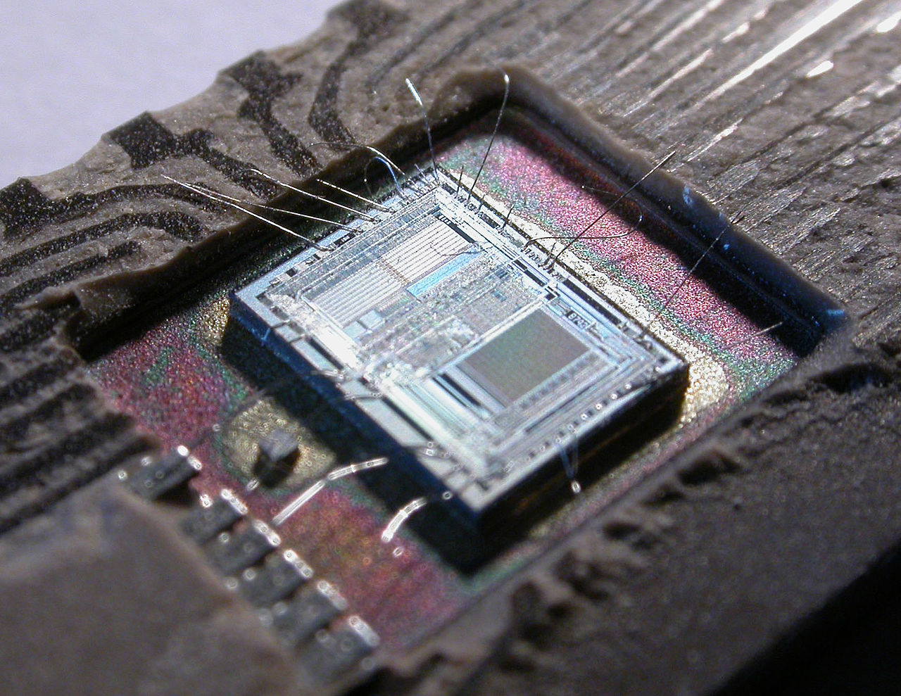
Basically these tiny devices (chips, uCs, micros, etc) are little baby computers. They tend to not run operating systems (like your laptop / pc / phone does), and contain much less compute power / memory.
I.E. while a generic laptop from 2021 will have ~ four cores running at 3GHz and ~ 4Gb of RAM (volatile memory, meaning it goes away when powered down), along with ~ 1Tb of disk (non-volatile memory, meaning it stays), microcontrollers will have between 8 and 800MHz of clock on one core, and between 32kb and 1Mb of volatile memory (typically SRAM), along with a similar amount of non-volatile memory (typically Flash: where we store programs, sometimes also EEPROM: where we store program data).
Additionally (and the whole reason for our bothering with these things) microcontrollers have peripherals - these are smaller, special function circuits that the computer-part of a microcontroller can interact with (via special function registers, more later) in order to operate on the physical world: setting voltages on external pins, reading and writing data to networks, reading data (or voltages) from sensors - etc. The microcontroller is our bridge between computing on data and computing on physical stuff.
Codes to instructions
In order to understand what-all is going on when we write code for a microcontroller, we need to understand a little bit about how code we write (in a human readable language) turns into “code” that can be executed by the computer: we have a “stackup” of abstracted layers that all work together whenever the program we wrote gets loaded into a microcontroller and does-stuff-in-the-world:
| layer / domain | layer | description |
|---|---|---|
| 1 / code | application code | the software you wrote! human readable, logical description of how the computer should operate |
| 2 / code | algorithm / library | other code modules; human readable, logical descriptions of generalized computing routines / sub-tasks |
| 3 / compiler | programming language | the set of syntax / logical rules that each layer above abides: naming, typing, order of operations, conditionals, etc |
| 4 / compiler | assembly language | a much “lower-level” (meaning less abstracted) programming language, where there is a very strong correlation between the language and the actual operating codes that the machine (cpu) reads… aka “symbolic machine code” |
| 5 / compiler | machine code | these are the actual instructions that a machine (cpu) will read: no symbols here anymore, these are the numbers that pass into the machines’ registers, and are operated on. |
| 6 / compiler | instruction set architecture | the ISA is to the machine code what a programming language is to our application code: it’s like a list of instructions that can be successfully interpreted by any cpu that “implements” the given ISA. |
| 7 / physics | micro architecture | the actual design / implementation / layout of gates, busses, registers, etc: the shape of the cpu / device. much like a circuit design, but probably fabricated with semiconductors |
| 8 / physics | devices (transistors) | n-p-n baby |
| 9 / physics | physics / matter / time / quarks | literal spacetime and matter propagating information / state about in the universe, now coordinated in order to do meaningful (to us) operations on voltage levels |
You don’t have to understand that whole set of layers, just that what we write a program in is a human-readable representation of what actually happens, which is that various numbers are shuffled around in the microcontroller’s memory, using the microcontroller’s brain. When we compile our code, it is transformed from this human-readable representation into the fabled “string of 1’s and 0’s” that the computer can operate on.
The “string of 1’s and 0’s” is what we call a binary file normally in .bin or .hex naming convention. In order for the microcontroller to operate on this binary file (and thereby run the program we’ve written) we need to load it into the microcontroller’s nonvolatile (normally flash) memory. This is why we often call programming a micro “flashing” it.
Programming / debug protocols
When a microcontroller wakes up (from a reset or powered-off state) it fetches its first instruction from the 0th address in its program memory. That instruction leads to the next, etc, booting the program. When we get a chip from the factory, that memory is empty and so the microcontroller doesn’t do anything! We need to write our freshly-compiled binary file (or a pre-compiled bootloader, or firmware update) into the memory, kind of like how we would write a file onto an SD card.
In order to do so, we need a relatively low-level data-writing protocol between our computer (where we’re compiling code / having binary files) and the microcontroller. The operation of these protocols is baked into the micro’s hardware and so it’s always available, but we normally need another tool in order for our computer to speak these protocols: most PCs have USB built-in, but not JTAG SWD or ISP etc.
Different chip families use different debug protocols, I’m keeping a list here of what you can expect to find in each family, including links for where you can purchase (or build) these tools, and pinouts!
Programming Protocol Reference Table
| protocol | pinouts | available programming tools | uCs / uC families |
|---|---|---|---|
| SWD (serial wire debug) / JTAG (joint test action group): |   | CMSIS-DAP tools | ATSAMD11, ATSAMD21 … any ARM-Cortex uC |
| ISP (in system programming) | 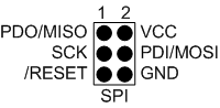 | atmel-ice spi fabISP arduino as isp | Atmel (now microchip) families: ATmega, ATtiny, etc |
| UPDI (unified programming debug interface) | 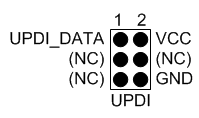 | USB to Serial tools | ATTINY412 … many new microchip uCs |
Toolchains
So in full order, we use a compiler to write a binary file, then use a programmer to write that binary file into the microcontroller. Together, these things constitute a toolchain - any sequence of tools used to turn code into a piece of operating firmware:
| device | protocol / link | device | protocol / link | device |
|---|---|---|---|---|
| personal computer: IDE and compiler | cmsis-dap over USB | the programmer: any CMSIS-DAP tool | over TTL | the microcontroller (aka device) (samd21, samd11) |
The whole family of these things (compilers, programmers, protocols) can be confusing, so I am maintaining this table of common microcontroller families, compilers and protocols we can use to write / load code with them, and their individual variants (i.e. most microcontrollers are available in a number of packages with different memories)… with some examples for each specific variant. Also (in the first column) should be some example codes for the micro for examples on how to operate their special function registers (explained two sections down).
This isn’t an exhaustive list, and it’s organized against chips that are common in the fab lab inventory. Links here should point you to more description of each layer or in some cases, setup instructions.
Micro Toolchain Reference Table
| chip family | toolchain setups | specific parts | example projects |
|---|---|---|---|
| ATSAMD11 | arduino + bootloader via cmsis-dap tools | ATSAMD11D | neil’s Echo board |
| ATSAMD11C | neil’s Echo board | ||
| ATSAMD21 | arduino + bootloader vscode/platformio + bootloader via cmsis-dap tools | ATSAMD21E18A | baby-ui-pad demo project fab-step Adafruit Gemma M0 (QFN package) |
| ATSAMD21G18A | SparkFun D21 Mini Breakout | ||
| ATSAMD51 | vscode/platformio + bootloader | ATSAMD51J19A | ucbus module Adafruit Feather M4 |
| ESP32 | |||
| NRF52 | |||
| ATTINY | arduino via updi tools | ATTINY412 | |
| ATTINY1416 | |||
| XMEGA | |||
| AVR |
Bootloaders
FWIW, adafruit covers bootloaders very well - they also write a lot of bootloaders.
Bootloaders are like “programming programs” (we love a little recursion, as a treat) or “flashing programs” - they’re bits of code that we stick in our microcontrollers that run for just a few ms at boot-up to check if there is a new program to load, and then loads it if this is the case. In this way, they “bootstrap” a program into their own memory.
Bootloaders live alongside the application code that we write, so they take up a little bit of space:
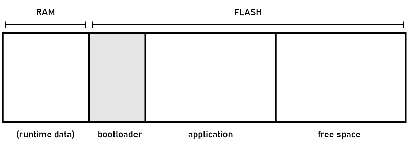
Basically, our SWD JTAG and ISP protocols are uncommon, and not a lot of people have an atmel-ice (or similar) tools lying around, so we use bootloaders to load programs using a communication protocol (like USB) that we are going to have on our circuit anyways. Since the bootloader is a real program, it can operate these higher level protocols just like any other firmware would.
Special Function Registers
So, by now we should understand how to program these things: we write human-readable code, our compilers turn that into a binary file that the actual CPU can parse, and we load it into the microcontroller’s memory via some special tool that writes directly into flash or with a bootloader.
However, we probably want to understand how actually the program we are writing interacts with the microcontroller’s pins and peripherals: like, how does some code that I wrote make the voltage on one of these pins go HI or LO? How is it that I can read a byte off of a UART port, or write one into it, and have that byte automatically turned into a stream of 1’s and 0’s on one of the pins? This is done via special function registers, or SFRs. It’s worth looking at a schematic representation of a micro, here the SAMD51
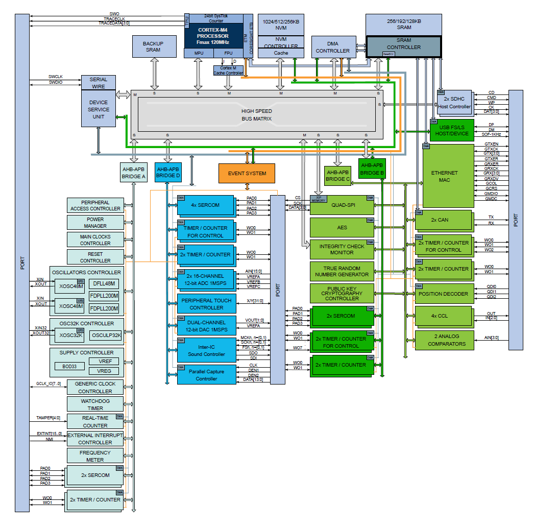
The dark blue near the top is the actual CPU - which as you can tell constitutes only a small section of the microcontroller’s complexity.
Everything else is a peripheral - some small circuit that performs a specialized function. In some regards, these are like little ASICs that are attached to the CPU. Some simply turn external pins ‘on’ or ‘off’ (pushing or pulling voltage), but most are more complex: they operate data protocols (SERCOMs here can run UART, SPI, or I2C), or timers (which count time, and also operate PWM), ADCs (analog to digital) and DACs (digital to analog), or USB, etc. Each of these runs independently of the cpu itself, meaning that the processor can do other stuff while the UART sequentially flips bits out of a port, or while a timer counts ticks, for example.
From a programmer’s perspective, we can think of these as little hardware “libraries” that are included on the microcontroller. Rather than an API, we operate them using pre-defined memory interfaces - when the CPU operates on specific addresses in the memory map, it is not simply writing data into memory, it is “flipping switches” on an interface to these peripherals. So, rather than making function calls to a library, our program reads and writes to specific (statically defined) bits in memory.
In one analogy I sometimes use, we can think of the cpu (or our program) as a little tiny human running around in a big ol’ factory: it’s thinking about the system operation. In order to interface with the machinery required to do the heavy lifting, there are switchboards all around where it can toggle buttons ‘on’ (1) or ‘off’ (0). This seems senseless until we remember that a data byte, which our program is familiar with, is just a series of bits. Here, the data byte doesn’t represent a number or a character, each bit is a switch.
Programming via SFRs is an ongoing pain, but it’s what we need to do in order to squeeze the maximal performance from our chips. Unlike software libraries, SFR codes are not portable between microcontrollers (even in the same family) - and the compiler has no idea what they’re doing: as far as it’s concerned, these are just more destinations in memory.
To help, we are maintaining some microcontroller hello-world code bases that give examples on how to interact with some of the more popular peripherals on the microcontrollers we use in the fab lab network… these links are included in the table above.
In Conclusion
Microcontrollers are wonderful and having a complete understanding of them can take years. I hope this tiny primer does decent work at de-mystefying some of the basics, and contains enough links / pointers to examples and setup guides such that it can help the novice hoping to build their first custom micro-controlled circuit, or serves as a handy reference for an expert looking for a toolchain example as they embark on a project with a new microcontroller family.
As always, GLHF!