SMT Circuit Manufacturing
In most fab labs, we encourage development of prototype circuits via circuit milling on the Roland Modela machines - this process was formalized when Bantam Tools (formerly Othermill) developed their circuit milling machine. Here is Ilan’s early milling machine and the MTM snap.
However, circuit milling can be cumbersome when we start working on more complicated projects, or need design tools like thermal vias and / or more than two layers.
So! Enter ‘board house’ fabrication. The PCB design and manufacturing industry is one of the most mature in terms of quoting speeds, turnaround times, and homogeneity in design files: all board houses will accept Gerber files describing board layers, and all circuit design tools will have built-in methods to export these formats. This means that ‘manufacturing as a service’ is straightforward for PCBs - we upload our Gerber files to a manufacturer’s website, and order the boards shipped to us.
Design Rules
Board houses will price out differently for different difficulties of manufacture, and all will have different limits to the number of layers, weights of copper, trace / space sizes, and drill sizes in your design. It’s nice to keep this in mind when you start in on a project. For some ‘rule of thumb’ limits:
| Trace | Space | Minimum Drill | |
|---|---|---|---|
| Coarse | 8mil / 0.2mm | 8mil / 0.2mm | 0.3mm |
| Medium | 6mil / 0.15mm | 6mil / 0.15mm | 0.2mm |
| Fine | 3mil / 0.1mm | 3mil / 0.1mm | 0.15mm |
Smaller traces / spaces are more expensive the heavier your copper weight is (the weight of copper per unit area on a board: the thickness) - as it’s more difficult to etch small gaps into thicker copper. Keep this in mind if you’re designing i.e. motor drivers, where heavier traces might be necessary.
Panelization
If you’re going to be producing boards in any appreciable volume, consider panelizing them. This just means arraying your design in a grid with edges so that you can run multiple instances of the circuit at a time in your Pick and Place machine (if you are using one), or, if you’re assembling by hand and the boards are small, you’ll be able to stencil solder paste onto more than one board simultaneously.
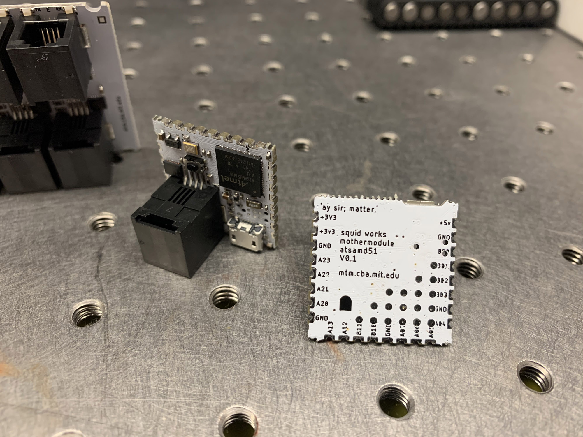
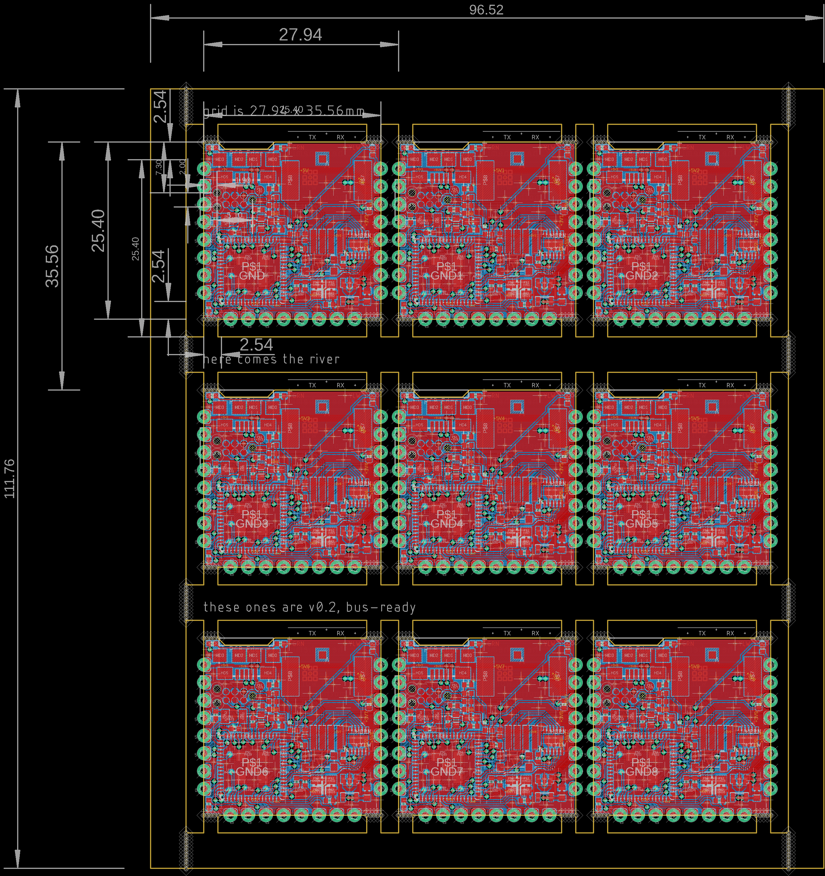
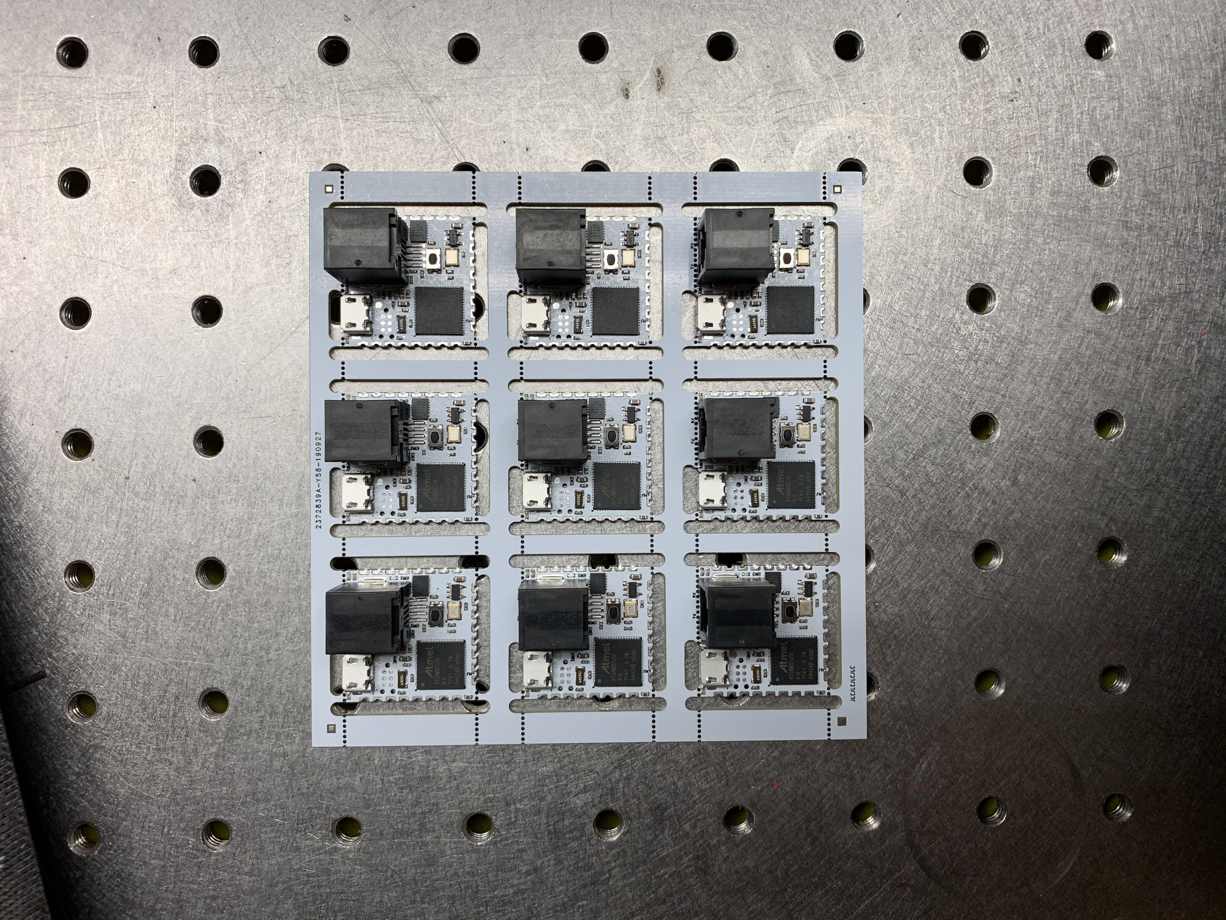
Panelization in CAD is a bit cumbersome, but is sometimes necessary if you have advanced board outlines. Here are some boards that I panelized by hand so that I could use castellated pins on the perimeter.
Generate Gerbers
Once you have a design and have checked that its design rules don’t violate your manufacturers guidelines, you’ll need to generate gerber files from whatever Electronics Design software you’re using.
Seeed Studio: Generate Gerber from Eagle
Seeed Studio: Generate Gerber from KiCAD
Quote and Ship
Now you just need to upload these files to your board house of choice, and wait for them to arrive. Here’s our list of vendors we’ve used:
On most of these quoting pages, you can specify copper weight, color, and whether / not you’d like your boards panelized by the house (which is easy when outlines are mostly rectangular).
If you want to reflow solder your boards, also order the stencil, which is your solder paste guide.
Stencils / Reflow Soldering
I gave up long ago on manually soldering every pin on my circuits by hand, since I have the luxury of a reflow oven. I always order the stencil with my boards (it’s often only ~ $10 extra dollars), and reflow using a toaster oven.
Check this video out for a better explainer on how to get into this. You’ll need an oven (or just a heat gun), solder paste, and a squeegee.
Placing
Depending on your component size, tweezers and a steady hand are enough to place components onto your board. Additionally, the solder’s surface tension will pull fine pitched components in-line when you reflow, so there’s some built-in error correction in the process.
The Oven
At the CBA, we’ve built a few controleo based ovens, but there are other ways to reflow.
Pick and Place
At the CBA, and in some Super Fab Labs, we have the Mechatronika M10V pick-and-place machine. For an intro on how to operate that machine, here is a good set of videos:
Mechatronika M10V 1
Mechatronika M10V 2
Mechatronika M10V 3
Mechatronika M10V 4
Mechatronika M10V 5
That’s It!
If you’ve made a few boards on a circuit milling machine, you might be surprised at how easy this is once you try it the first time. The added lead time on your circuit is something of a pain, but if you’re patient in the design cycle, and double check your data sheets, it’s often less time to do this than to rush to the milling machine to make a prototype circuit.